
Блог переводчика-провизора
О фармацевтическом переводе и не только
Dose, dosage, доза, дозировка |
||||
|
Доза — количество лекарственного препарата (действующего вещества) на один прием. Слово «дозировка», по-видимому, происходит от слова «дозировать» и обозначает не только количество ЛП на один прием, но и количество приемов, продолжительность применения и пр. (все указания врача по приему препарата). Надо сказать, что «дозировка» — термин более расплывчатый, нежели «доза». Суточная, курсовая, терапевтическая, высшая разовая, высшая суточная… — все это дозы, а не дозировки. Но иногда слово «дозировка» употребляют и в значении «доза». Переводчикам я советую для ясности этого избегать. Запомнить различие достаточно просто. Доза — это только количество. Дозировка — это процесс (продолжительность, кратность приема), дозирование. Под дозировкой также понимают содержание действующего вещества в единице лекарственной формы (таблетке, капсуле, суппозитории и пр.). В английском, к счастью, dose соответствует дозе, а dosage — дозировке (см. пояснение на английском). Дозирование — dosing. И еще: Dosing regimen (dosage regimen) — режим дозирования. Включает в себя все то, что входит в понятие «дозировка». Dose adjusment — коррекция дозы (пациент принимал 5 мг 2 раза в день, а стал принимать 10 мг, но также 2 раза в день). Dosage adjustment (dosing adjustment), соответственно, будет переводиться как «коррекция дозировки» (например, изменяется кратность приема препарата). Хотя, если задуматься, коррекция дозировки в итоге все равно приводит к коррекции дозы (только не разовой, а суточной или курсовой, например). Может, поэтому чаще говорят все-таки о коррекции дозы? Если не уверены в деталях, пишите лучше «коррекция дозы». |
||||
|

The 8-pin 25Q32 IC holds the firmware. The schematic shows the SPI communication lines (CS, CLK, DIO, DO) connected directly to the main processor.
: If an LED strip breaks or short-circuits, feedback resistors detect an over-voltage or under-current anomaly and trigger a shutdown to prevent fire hazards. 4. System Logic and Display Interfaces
The TP.V56.PB801 is an extremely common "three-in-one" (3-in-1) mainboard found in a vast array of LED televisions, particularly from smaller or "off-brand" manufacturers, but also in models from recognizable names like Elenberg, Chigo, Orion, and Fusion. Its popularity stems from its all-in-one design, which integrates the power supply, LED backlight driver, and main processor onto a single printed circuit board (PCB).
is a combo board that combines the mainboard, driver board, and power supply unit into a single PCB. It is commonly found in 15-32 inch LCD/LED televisions and monitors. Key features include: Typically uses the TSUMV56RUET-Z1 chipset.
For those interested in learning more about the Tp.v56.pb801 Schematic Diagram and schematic diagrams in general, there are several resources available:
The TP.V56.PB801 is one of the most widely used three-in-one LCD/LED TV mainboards in the electronics repair industry. Manufactured by BoardTech (and various OEM facilities), this board integrates the main processor, a LED backlight driver circuit, and a power supply unit (PSU) onto a single substrate. It is commonly found in budget-friendly television brands ranging from 24-inch to 42-inch panel sizes.
: A fuse, varistor (VDR), and negative temperature coefficient (NTC) thermistor guard against overcurrent and voltage spikes.
Native 1366x768 (HD) or 1920x1080 (Full HD).
Detailed schematic PDFs and service manuals are often hosted on technical repositories like Elektrotanya or Scribd for professional reference. Universal TV Driver Board Installation and User Manual
The board operates on a 12V DC input. The power section utilizes DC-DC buck converters to step down the input voltage to the levels required by the Main Processing Unit (MPU).
From 1024x768 up to Full HD (1920x1080 @ 60Hz) 2. Architecture Breakdown of the TP.V56.PB801 Schematic
A jumper or circuit that allows switching the LVDS supply voltage between 3.3V, 5V, or 12V. 5. IR and Keypad Connector
Do not turn off the power. Wait until the LED stops blinking and turns solid red. Method B: ISP Programmer Flashing
The primary source for the schematic diagram is a resource page on radio-files.ru , which provides a PDF file containing the full electrical schematic, typically hosted on a Yandex Drive link.
Boosts voltage to drive the LED backlight strips, typically ranging from 40V to 60V with a current of around 520mA . Audio Power Amplifier: Drives the internal speakers.
The hot side of the schematic deals with high-voltage AC mains rectification.
The Tp.v56.pb801 Schematic Diagram has several applications in various fields, including:
Англоязычные интернет-ресурсы по анатомии, физиологии и патологии нервной системы человека |
||||
|
Организаторы курса Medical Neuroscience и студенты собрали множество полезных ресурсов по неврологии. Хочу поделиться с вами наиболее ценными из них. Все ресурсы на английском (есть два платных, остальные бесплатные). Сразу оговорюсь, что я далеко не все подробно изучала. Учебники — основной учебник курса под названием Neuroscience (5-е издание 2012 г.). В рунете можно найти отсканированное предыдущее издание (2008 г.). Книга дополняется сайтом, где, уже бесплатно, можно посмотреть анимации по многим тематикам и пройти тесты по книге. Там же есть толковый словарь; — онлайн-учебник по неврологии Техасского университета. У меня почему-то в Chrome не хватает плагинов для просмотра интерактивных элементов (и не пишут каких). Может, кто-нибудь подскажет, как с этим справиться? — еще два онлайн-учебника, Колумбийского университета и Вашингтонского университета. На любой вкус :). Анатомия — интерактивный анатомический атлас Sylvius 4, доступ платный. Атлас разработан авторами книги, и преподаватель Medical Neuroscience пользуется им на лекциях. Я доступ к атласу не покупала, потому что не было времени его изучать, но сделано все очень хорошо. Впрочем, есть и множество бесплатных ресурсов; Tp.v56.pb801 Schematic Diagram — атлас ствола головного мозга; — анатомия поверхности головного мозга в 3D. Сайт http://www.g2conline.org/, раздел 3D Brain; — еще один интерактивный атлас головного мозга и спинного мозга (МРТ, гистология, объемные препараты, 3D); — атлас головного мозга (срезы, гистология, МРТ, 3D и многое другое); — и еще один интерактивный атлас (Колумбийский университет. Интересно, у нас сколько университетов, создающих подобные ресурсы?); — модель головного мозга в 3D, программа для компьютера; The 8-pin 25Q32 IC holds the firmware — еще одна 3D-модель головного мозга; — еще одна 3D-модель и много других анимаций по работе нервной системы; — снова МРТ головного мозга (Дюкский университет, организаторы курса); — анатомия головного мозга в срезах; — презентация по анатомии спинного мозга; is a combo board that combines the mainboard, — атлас головного мозга в период эмбрионального развития; — своеобразный интерактивный учебник, который можно использовать для проверки знаний (Университет Юты). Патология — презентации: поражения ствола мозга и спинного мозга; — анатомия головного мозга с кратким экскурсом в патологию; И в качестве бонуса — подкасты по неврологии на NEURO.tv. |
||||
|
Терминология клинических исследований |
||||
|
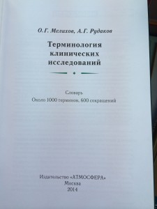
Увидела сегодня в Доме книги на Фрунзенской англо-русский словарь по клиническим исследованиям. Вышел в 2014 г., издан качественно (в руках держать приятно), небольшого формата. Ниже фотографии из магазина:
В Доме книги он стоит (внимание!) 1705 руб. (Пруф.) На сайте издательства — 900 руб, а за 350 руб. можно купить электронную версию в pdf (что я и сделала; дополню пост, когда получу файл). Я это выяснила за 2 минуты, стоя в магазине :). У тех же авторов есть еще книга по клиническим исследованиям, стоит столько же. Я еще тоже купила в комплект к словарю, потом поделюсь впечатлениями. |
||||
|


Tp.v56.pb801 Schematic Diagram Guide
The 8-pin 25Q32 IC holds the firmware. The schematic shows the SPI communication lines (CS, CLK, DIO, DO) connected directly to the main processor.
: If an LED strip breaks or short-circuits, feedback resistors detect an over-voltage or under-current anomaly and trigger a shutdown to prevent fire hazards. 4. System Logic and Display Interfaces
The TP.V56.PB801 is an extremely common "three-in-one" (3-in-1) mainboard found in a vast array of LED televisions, particularly from smaller or "off-brand" manufacturers, but also in models from recognizable names like Elenberg, Chigo, Orion, and Fusion. Its popularity stems from its all-in-one design, which integrates the power supply, LED backlight driver, and main processor onto a single printed circuit board (PCB).
is a combo board that combines the mainboard, driver board, and power supply unit into a single PCB. It is commonly found in 15-32 inch LCD/LED televisions and monitors. Key features include: Typically uses the TSUMV56RUET-Z1 chipset.
For those interested in learning more about the Tp.v56.pb801 Schematic Diagram and schematic diagrams in general, there are several resources available:
The TP.V56.PB801 is one of the most widely used three-in-one LCD/LED TV mainboards in the electronics repair industry. Manufactured by BoardTech (and various OEM facilities), this board integrates the main processor, a LED backlight driver circuit, and a power supply unit (PSU) onto a single substrate. It is commonly found in budget-friendly television brands ranging from 24-inch to 42-inch panel sizes.
: A fuse, varistor (VDR), and negative temperature coefficient (NTC) thermistor guard against overcurrent and voltage spikes.
Native 1366x768 (HD) or 1920x1080 (Full HD).
Detailed schematic PDFs and service manuals are often hosted on technical repositories like Elektrotanya or Scribd for professional reference. Universal TV Driver Board Installation and User Manual
The board operates on a 12V DC input. The power section utilizes DC-DC buck converters to step down the input voltage to the levels required by the Main Processing Unit (MPU).
From 1024x768 up to Full HD (1920x1080 @ 60Hz) 2. Architecture Breakdown of the TP.V56.PB801 Schematic
A jumper or circuit that allows switching the LVDS supply voltage between 3.3V, 5V, or 12V. 5. IR and Keypad Connector
Do not turn off the power. Wait until the LED stops blinking and turns solid red. Method B: ISP Programmer Flashing
The primary source for the schematic diagram is a resource page on radio-files.ru , which provides a PDF file containing the full electrical schematic, typically hosted on a Yandex Drive link.
Boosts voltage to drive the LED backlight strips, typically ranging from 40V to 60V with a current of around 520mA . Audio Power Amplifier: Drives the internal speakers.
The hot side of the schematic deals with high-voltage AC mains rectification.
The Tp.v56.pb801 Schematic Diagram has several applications in various fields, including:
Pinnaclego © 2026